I have 2 HP ESP120 Power supplys and one of them I use on my 2m amplifier in the upstairs shack.
This only because I do not have 3 phase outlet in that shack for a Delta SM70-45 power supply which I use for the 70cm EME amplifier.
Have made some study of how others are enabling the ESP120 and I am a bit puzzled how they do.
The most used way seems to be published by N4GA where he advice to short out 3 pins without any description of their functionality.
I read the only datasheet I could find on a similar power supply that looked like a drop in replacement for the HP supply.
This shows that when connecting these three pins together you short out Power on, PSKILL and the present pins.
PSON is the remote control input connector.
PSKILL is a emergency kill pin that switch the PS off if it looses connection to the 5V rtn.
Present pin is an indicator for the system to show that a PS is inserted in that slot.
Connecting these pins do not seems correct and I am actually surprised it works but it does.
Only reason I can se is that if the Present pin have an internal path to ground.
In my mind I would connect the PSKILL to the 5V rtn constantly and switch the PSON to 5V rtn to enabel the PS output and I tested to do so and it worked perfectly.
The reason for all this was that I wanted to remotely control the PS from the amplifier and when connecting the Power on switch of the amplifier between the PSON to 5V rtn it works great.
I have occasionally seen some noise from the PS on 2m. but I placed capacitors on the output connections to PS outer cover and also placed a copper braid screen around the two 10 mm Square cables to the amplifier and grounded that in the outer housing as well.
This seems to fix the worst noise but its important to ensure the cables are routed in a specific way to totally get rid of any noise.
This is most likely caused by the fact the 2m antenna is placed only 4 meters above the shack where the PS is located.
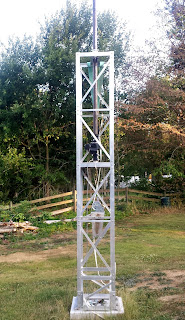
Got a half promise that a friend with an excavator will come this or next week to fill the whole for the concrete base and to dig down the anchor points for a 22m mast I have laying to use for tropo and a HF beam.
Tuesday 31 July 2018
Friday 27 July 2018
Slow progress
Have cut and trimmed all elements and drilled the booms and everything is prepared for mounting but the weather is just to hot at the moment.
The temperature is above 30 in the shade every day and outdoor work not possible at the moment.
Have done some other work like rebuilding the kitchen and spending time relaxing with the family.
Did some cleaning and maintenance of the machines in the workshop as well.
Bought 6mm dipole holder but have designed my own ones and will print a few to evaluate RF performance of the PLA material.
When drilling the booms I discovered that on 2 of the antennas the 2nd director was slightly shifted to one side so I need to go through all antennas to ensure they are assembled correctly.
Don't think it happend over time and It's a error from my side when assembing the antennas last year.
I also awaits the support wires I ordered earlier to try out how the support structure will end up like.
Assume it will be ok using one support wire going from the front of the boom to the back and have a turnbuckle in the back to allow adjusting tension.
The feedstructure will hopefully be enaugh support between the antennas in the back and if needed I will order some fiberglass support for the front but I want to assemble it all together first to evaluate.
Wednesday 11 July 2018
Antenna rebuild finally started.
Now I have started the antenna rebuild now and it is going fairly well.
Measured all antennas and they are similar to each other and the cables seems ok too but they have been drying in the massive drought we have at the moment.
Had 7mm rain for the last 2.5 month and all grass is burned and the leafs are falling from the trees.
After testing the antennas I made a bent dipole to check how it behaves.
Did not find any 6mm copper tubing but 4.6mm so I built one with that and it worked quite well.
Made a 1/2 lambda impedance transformer and a 1/2 lambda feeding cable and tuned it to 432 MHz.
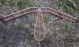
With the dipole at the same position as the old one it needed som fine tuning of bending angle but the end results was very good and the same as the old.

Resonance is close to exacltly as simulated and matching is very good.

Earlier I removed the 6m mast and lowered it so I can reach the feeding of the 25 element yagis standing on the ground .
Think its a good idea when elaborating how the feeding shall be.
Needed to rebuild the base mounting too as it was not fully stable.
Measured all antennas and they are similar to each other and the cables seems ok too but they have been drying in the massive drought we have at the moment.
Had 7mm rain for the last 2.5 month and all grass is burned and the leafs are falling from the trees.
After testing the antennas I made a bent dipole to check how it behaves.
Did not find any 6mm copper tubing but 4.6mm so I built one with that and it worked quite well.
Made a 1/2 lambda impedance transformer and a 1/2 lambda feeding cable and tuned it to 432 MHz.

With the dipole at the same position as the old one it needed som fine tuning of bending angle but the end results was very good and the same as the old.

Resonance is close to exacltly as simulated and matching is very good.

Earlier I removed the 6m mast and lowered it so I can reach the feeding of the 25 element yagis standing on the ground .
Think its a good idea when elaborating how the feeding shall be.

Needed to rebuild the base mounting too as it was not fully stable.
Will continue the next few days cutting and tuning the elements for the vertical yagis and drill the booms as well.
The garage has been locked due to a broken exhaust manifold on the Buick so I have not been able to drill any booms but that is sorted now thanks to my helpfull neighbor.
Subscribe to:
Posts (Atom)